Benefits of Designing & Drafting
Designing and drafting using Computer-Aided Design and Drafting (CADD) has many benefits! It allows for precise and accurate drawings, faster design iterations, easy modification, and efficient collaboration. CADD also helps save time and resources, improves visualization, and enhances overall productivity. It’s a powerful tool for professionals in fields such as architecture, engineering, and manufacturing.
Examples of the benefits of designing and drafting using CADD:
- Precise and Accurate Drawings: With CADD, you can create detailed and accurate drawings, ensuring that measurements and dimensions are precise. This helps in avoiding errors and ensures that the final design meets the required specifications.
- Faster Design Iterations: CADD allows for quick and easy modifications to designs. You can make changes, experiment with different ideas, and iterate designs much faster compared to traditional manual drafting methods. This helps in saving time and allows for more efficient design processes.
- Efficient Collaboration: CADD software enables seamless collaboration among team members. Multiple people can work on the same design simultaneously, making it easier to share ideas, provide feedback, and make real-time changes. This enhances teamwork and improves overall productivity.

SolidWorks can also be used for Business Purposes
Let me give you an example of how SolidWorks can be used for business. Imagine you’re a product design company that specializes in creating innovative consumer electronics. With SolidWorks, you can design and visualize your product ideas in 3D.
Let’s say you’re developing a new smartphone. Using SolidWorks, you can create a detailed 3D model of the phone, including its exterior design, internal components. This allows you to see how the phone will look and function before any physical prototypes are made.
But it doesn’t stop there! SolidWorks also helps you with the manufacturing process. You can generate accurate manufacturing drawings that provide all the necessary dimensions and specifications for each component of the phone. This ensures that your manufacturing partners can produce the phone exactly as intended.
Additionally, SolidWorks offers simulation capabilities. You can simulate how the phone will perform in different scenarios, such as drop tests or thermal analysis. This helps you identify potential issues and make improvements to ensure the phone meets quality standards.
Once your design is finalized, SolidWorks allows you to create stunning visuals and animations to showcase your product. You can create realistic renderings of the phone, highlighting its sleek design and features. These visuals can be used in marketing materials, presentations, and even on your website to attract customers.
So, you see, SolidWorks is not just a tool for engineers and designers, but it’s also a valuable asset for businesses. It helps streamline the product development process, improve collaboration, and bring innovative ideas to life.

SolidWorks is a computer-aided design (CAD) software that helps engineers, designers, and architects create 3D models of their designs. It’s widely used in various industries, including manufacturing, automotive & aerospace.
With SolidWorks, you can create detailed 3D models of parts, assemblies, and even entire buildings. It provides a user-friendly interface with a wide range of tools and features to make the design process easier and more efficient.
One of the key features of SolidWorks is its parametric modeling capability. This means that you can define the dimensions and relationships of your design using mathematical parameters. If you change a parameter, the software automatically updates the entire model accordingly, saving you time and effort.
SolidWorks also offers a variety of tools for creating complex geometries, such as fillets, chamfers, and drafts. You can also add features like holes, threads, and patterns to your designs. The software provides a library of standard parts and materials, making it easy to incorporate them into your models.
Collaboration is made easy with SolidWorks. You can share your designs with colleagues or clients, allowing them to view, comment, and make suggestions. The software also supports integration with other engineering tools, such as finite element analysis (FEA) and computational fluid dynamics (CFD) software, for advanced simulations and analysis.
SolidWorks is a powerful tool that can greatly enhance the design process, from concept development to final production. It helps streamline workflows, improve accuracy, and reduce errors. Whether you’re designing mechanical parts, architectural structures, or anything in between, SolidWorks can be a valuable asset.
Various applications of SolidWorks in more detail!
- Mechanical Engineering: SolidWorks is extensively used in mechanical engineering for designing and analyzing mechanical components, machinery, and systems. It allows engineers to create 3D models of parts, assemblies, and mechanisms, enabling them to visualize and test their designs before manufacturing. SolidWorks also offers simulation capabilities to perform stress analysis, motion analysis, and thermal analysis, ensuring that the designs meet the required performance and safety standards.
- Product Design and Development: SolidWorks is a go-to software for product designers and developers. It enables them to create realistic 3D models of their product concepts, iterate on designs, and visualize how the product will look and function. SolidWorks also allows for easy collaboration between design teams, stakeholders, and manufacturers, facilitating a smoother product development process.
- Aerospace and Defense: SolidWorks plays a crucial role in the aerospace and defense industries. It helps engineers design aircraft components, such as wings, fuselages, and landing gear. The software’s simulation capabilities are used to analyze the structural integrity, aerodynamics, and performance of the aircraft. SolidWorks also aids in the development of defense systems, such as military vehicles, weapons, and communication devices.
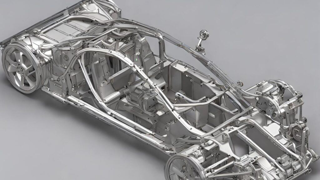
- Automotive Industry: SolidWorks is widely used in automotive design and engineering. It assists in creating 3D models of vehicle parts, assemblies, and systems, including engines, chassis, and interiors. Engineers can simulate the behavior of the vehicle under different operating conditions which can help them to optimize designs for weight reduction eventually increasing the fuel efficiency. It also helps in perform crash and safety analysis to ensure compliance with industry regulations and safety laws.
- Education and Research: SolidWorks is widely used in educational institutions for teaching engineering and design principles. It provides students with hands-on experience in 3D modeling, simulation, and design analysis. SolidWorks also supports research activities in various fields, such as biomechanics, material science, and robotics, enabling researchers to develop innovative solutions and conduct virtual experiments.
What are Assemblies in SolidWorks
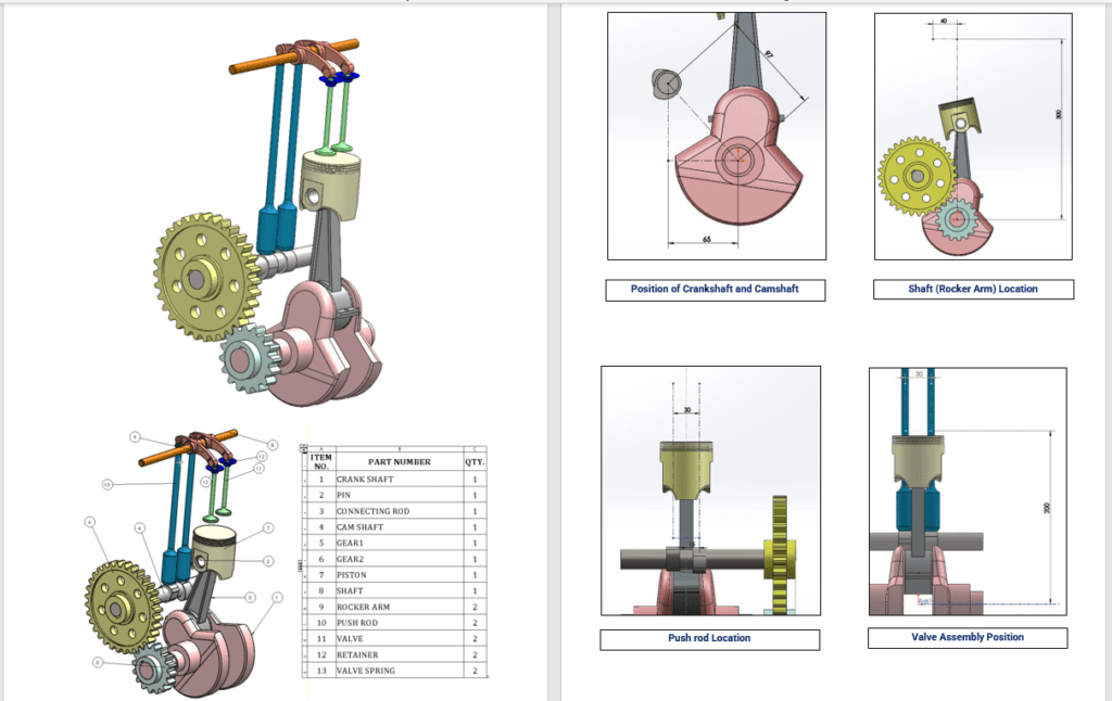
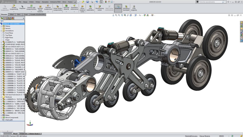
In SolidWorks, assemblies are a way to bring multiple parts together to create a complete product or system. It allows you to simulate the interaction between different components and check for any interferences or clashes.
To create an assembly in SolidWorks, you start by inserting the individual part files into a new assembly file. You can then position and mate the parts together using various constraints such as coincident, concentric, and parallel. This ensures that the parts are aligned and connected correctly.
Once the assembly is created, you can perform various operations on it, such as rotating, translating, or animating the components to see how they perform and provide functional output. You can also apply materials, textures, and appearances to the assembly to visualize the final product.
SolidWorks provides tools for analyzing the assembly, such as checking for interference between components, calculating mass properties, and running motion simulations. This helps in identifying any issues and optimizing the design before manufacturing.
Overall, assemblies in SolidWorks allow you to create complex 3D models, simulate their behavior, and visualize the final product. It’s a powerful tool for designing and engineering assemblies in industries like manufacturing, automotive, and aerospace.

Top-Down Approach
- The top-down approach is a design methodology where you start with the overall system or product and then break it down into smaller components or subsystems. You define the high-level requirements and specifications first, and then design each component to meet those requirements. This approach allows for better integration and coordination between different parts of the system.
- For example, let’s say you’re designing a car. With the top-down approach, you would start by defining the overall requirements for the car, such as its size, performance, and features. Then, you would break it down into subsystems like the engine, chassis, electrical system, and interior. Each subsystem would be designed separately, keeping in mind how they will fit together to create the final car.
Bottom-Up Approach
- The bottom-up approach is a development methodology where you start with individual components or modules and gradually build them up to create the entire system. You begin by designing and developing the smallest components, and then gradually combine them to create larger subsystems and the overall system.
- Continuing with the car example, with the bottom-up approach, you would start by designing and developing individual components like the engine, tires, and seats. Once each component is ready, you would assemble them together to create subsystems like the powertrain, suspension, and interior. Finally, you would combine these subsystems to build the complete car.
Both approaches have their advantages and disadvantages, and the choice between them depends on factors such as project complexity, time constraints, and team expertise. The top-down approach focuses on the overall system design and integration, while the bottom-up approach emphasizes component development and gradual assembly.
Tips for Assemblies
Lightweight Assemblies option/setting:
- It helps to optimize performance by shutting down the corner edges, which can reduce the complexity of the design and make it easier to work with.
- Rendering can be lower, meaning that the level of texture effects can be adjusted to improve performance without sacrificing the overall visual quality.
- Unnecessary parts can be hidden until they are selected, making it easier to focus on specific components and improve productivity.
- It also helps to lower the graphics requirements, which can be beneficial for smoother operation and improved performance.
Large Assemblies option/setting:
- When dealing with large assemblies that consist of thousands of parts, it’s often beneficial to break them down into smaller sub-assemblies. This helps with organization, simplifies the design process, and improves overall efficiency.
- Example a complete assembly of 1000 parts can be divided into three or more Sub-assemblies making modification or changes easier and faster. it also helps load parts separately rather than loading all 1000 parts in a single go.

Single Part
- If there are parts within the assembly that don’t require mechanical motion or output, combining them into a single part can be a smart approach. This reduces complexity and streamlines the assembly, making it easier to work with.
- By utilizing sub-assemblies and consolidating non-mechanical parts, designers can optimize their workflow and create more efficient designs.
Suppress
- “Suppress” is a unique feature helping to completely disable a unnecessary part in a complete assembely.
- Imagine you have a complex assembly with multiple components, and you want to focus on a specific part. By using the “Suppress” feature, you can hide or disable the other components temporarily, allowing you to work on the selected part without any distractions. This can help you streamline your design process and make it more efficient.
Copy with mates (Mirror Effect)
- When you want to create multiple copies of a component in SolidWorks while maintaining specific relationships or constraints between them, you can use the “Copy with Mates” feature. It allows you to duplicate a component and automatically apply the same mates or relationships to the copies.
- For example, if you have a bolt mated to a hole, you can use “Copy with Mates” to duplicate the bolt and automatically apply the same mating conditions to each copy. This saves you from manually reapplying the mates for each bolt, making your design process more efficient.
